- Projects
- Insights
-
Careers

Careers
Ranked a Top Workplace and ENR Top 500 Design Firm, Burns offers opportunities to inspire, create and deliver transformational projects that last generations.
- News + Events
-
About

About
Burns inspires, creates and delivers specialized-engineering solutions for mission-critical facilities.
- Offices
-
What We Do
Discipline
Expertise
Industry-Specific - Projects
- Insights
- Careers
- News + Events
- About
- Offices
"*" indicates required fields
Smooth Airport Expansions Start Underground: Integration of Utility Planning in Civil Infrastructure Design
Modern airports are constantly evolving. From terminal improvements and expansions to new airfield taxiways and runways, it seems construction never ends. However, the aging underground utility systems within these projects are frequently left untouched unless they are directly impacted by new construction or renovation. Little thought is given to their condition, age, or future capacity.
Utilities are vital to airport operations. Understanding the condition and future needs of these systems is necessary for annual improvements and ongoing capital work as well as smooth airport expansion. With the increasingly widespread adoption of GIS databases and digital twins, maintenance and operations staff are able to gain a comprehensive view of utility systems, enabling them to troubleshoot more efficiently, plan preventive maintenance, and schedule upgrades and replacements. This reduces operational costs and enables staff to proactively maintain buildings, rather than reacting to emergencies. Advancing site utility planning and modeling outside buildings in parallel will yield similar benefits, empowering clients to focus on daily maintenance and further control costs.
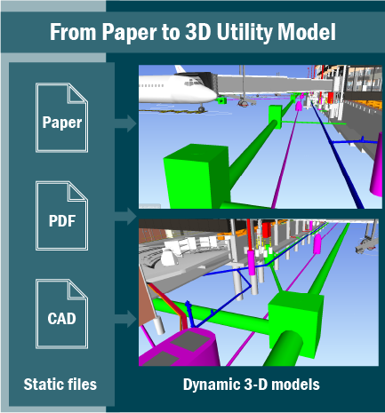
An accurate understanding of the existing system, current trends, and future needs is necessary to plan utility infrastructure. To begin master planning, understanding current utility conditions is essential. Transitioning from traditional construction design documents and as-builts to data based design is a critical step. Designers, contractors, and operations staff all benefit from this shift. It requires replacing CAD, paper, and PDF plans with data-rich 3D utility models. These models support future planning, expansion, maintenance assessments, and failure prevention.
Moving from Traditional 2D Design to 3D Design
Understanding the accurate location of existing utilities and modeling them is crucial to every step in the process. The first step is integrating historical design or as-built paper or PDF utility and underground infrastructure plans, or 2D AutoCAD design drawing files into a 3D model like Revit or Civil 3D to detail the complexity of the utility networks. The 3D model created from existing documents details the complexity of the utility networks and accurately maps the various systems. This helps designers understand their horizontal and vertical relationships under existing roads, facilities, or airfield pavements and understand their use in the maintenance and operation of existing utilities and infrastructure and the planning, design, and construction of new infrastructure and utilities.
Entering existing utility data involves capturing information from current, past, and future construction efforts. This includes equipment manufacturer and models, installation dates, contract numbers, and material specifications including pipe type and thickness or structural wall dimensions. While this information may not always be readily available in existing documents, creating a workbench in the 3D model that integrates with a GIS database is critical for that data to be used in future design, operations, and maintenance.
Although the process of transferring data from paper, PDF, and CAF files to create the 3D model may be labor-intensive, it is critical to creating an accurate and reliable model. This model serves as a foundation for future design teams and contractors, ensuring their work—whether it is utility tie-ins, crossings, or access for maintenance—is based on up-to-date information. This accuracy prevents costly field changes, redesigns, and construction delays caused by unforeseen subsurface utility conditions. It also enables design teams and owners to make informed decisions about tie-in locations, work limits, phasing, and scheduling, helping to avoid disruption to ongoing operations.
Coordinating Site and Facility Design
By integrating civil design within a 3D model, design teams can coordinate site utilities directly with utility connection points to mechanical and electrical rooms within buildings. Coordination points for site utilities often end 5-10 feet from the building and building utilities extend 5-10 feet outside the building. While this is a definable coordination location, it doesn’t mean it’s easily coordinated, or that everyone is working with the same base point. As everyone who has worked on a facility design project knows, coordination is not a fully automated process. 3D models that capture site and facility utility models and flag conflicts are produced using programs such as Civil 3D, Revit, and Navisworks, which act as a digital coordinators. They produce graphics that are easily understood by designers and non-engineers.
The 3D modeling of existing and proposed site utilities improves coordination between disciplines and improves future planning capabilities. It furthers an airport’s ability to implement and utilize GIS and Asset Management software to operate and maintain its infrastructure long into the future.
Proactively Planning for the Future
Integrating 3D models using software such as Civil 3D, Revit, and Navisworks into site utility planning for airport infrastructure delivers unparalleled accuracy, coordination, and future-readiness. Developing 3D models of existing and proposed utilities creates a dynamic, living model that evolves with the airport itself that has innumerable uses. With precise and continuously updated utility data, planners, engineers, contractors, and operations teams can model the impacts of future expansions, evaluate capacity, simulate redundancy and resiliency scenarios, and proactively plan for preventive maintenance.
To fully realize these benefits, airport authorities and project stakeholders must prioritize the adoption of integrated 3D utility modeling workflows as a foundational component of infrastructure planning and design.